Rapid Impact CompactionRapid Impact Compaction (RIC) is an ideal method for increasing soil compaction and bearing capacity and reducing the settlement and the risk of liquefaction in loose Sands. This method is fast and economical and is environmental friendly.
Introduction
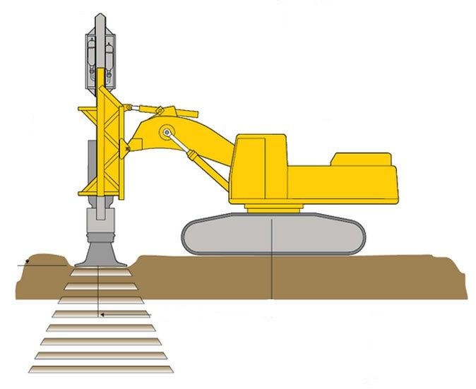
Basic Concept Rapid impact compaction is an intermediate compaction method between conventional shallow compaction and deep dynamic compaction. It densifies geomaterial by repeatedly dropping a hydraulic hammer mounted on an excavator at a fast rate as shown in
Figure 1. The weight of hammer is typically 5–12 tons, which is dropped freely from a height of 1.2 m on a circular steel foot with a diameter of 1.0–1.5 m (the most common one is 1.5 m in diameter). The rapid impact. compaction machine can generate 40–60 blows per minute,
which is much faster than the deep dynamic compaction machine. There is a monitoring system on the machine to record impact energy and foot penetration. The depth of improvement depends on geomaterial type and properties, groundwater table level, and applied energy. This technology has been adopted since its initial use in the United Kingdom in 1990s (Adam and Paulmichl, 2007). The production rate of each machine is up to 500 m2 improvement area per day.

Suitability This method is generally suitable for granular geomaterials, including gravel, sands, silts, uncontrolled fills (i.e., a mixture of sand, silt, and clay), and industrial and mine wastes. It has also been successfully used to minimize collapsible potential of loess. This method generally can improve geomaterials up to a depth of 6mdeep (mostly 3–4m).
Applications Rapid impact compaction has been used for increasing bearing capacity and stiffness of geomaterial to support building foundations, floor slabs, tanks, highways, railways, parking lots, and airport runways, mitigating liquefaction, and reducing waste volume and collapsible potential. It has also been used to compact granular fills in large lifts (up to 3 m).
Advantages and Limitations The operation of rapid impact compaction is fast and under a much controlled manner as compared with deep dynamic compaction. It induces smaller vibrations than deep dynamic compaction due to low impact energy; therefore, it can be operated at closer distances to existing structures. Because the impact foot is always in contact with the ground, it eliminates the risk of generating flying debris. Similar to deep dynamic compaction, it can detect weak areas during the construction. It has better mobility and works in areas with difficult access. The key limitation for this technology is that the depth of improvement is smaller than that of deep dynamic compaction.
Principles
Rapid impact compaction ismainly used for granular geomaterials. Its general principle is dynamic densification, which is similar to that for deep dynamic compaction when used to densify granular geomaterials. Since rapid impact compaction has lower single-drop energy with a larger number of drops, the densification of geomaterial is progressive and accumulated. BRE (2003) and Serridge and Synac (2006) explained the progressive densification by a concept of soil plug, which is different from that of deep dynamic compaction. In deep dynamic compaction, deeper geomaterial is densified first by tamping at larger spacing and then shallow geomaterial is densified by tamping at smaller spacing. Serridge and Synac (2006) referred to this densification process as a “bottom-up” process. In rapid impact compaction, however, a dense soil plug is first formed under the steel foot by the first few blows. Further blows push the dense geomaterial plug as a rigid block deeper to densify the underlying geomaterial until no or little further penetration can be achieved. This process is referred to as the “top-down” process by Serridge and Synac (2006). This densification process can be used to explain why rapid impact compaction can densify geomaterials at deeper depths even though its single-drop energy is much lower than that by deep dynamic compaction. It is important to point out that in rapid impact compaction, the accumulated impact energy has more influence on the depth of improvement than the single-drop energy. Since rapid impact compaction can densify the geomaterial directly below the steel foot, impact points at close spacing are necessary.
Design Considerations
Depth of Improvement Due to the different densification processes by deep dynamic compaction and rapid impact compaction, the formula to estimate the depth of improvement for deep dynamic compaction
cannot be used for rapid impact compaction. BRE (2003) and SAICE (2006) provide the guidelines to estimate the depth of improvement for rapid impact compaction as shown in Tables 1 and 2.
| Geomaterial |
Applied Energy (ton-m/m2) |
Depth of Improvement (m) |
| Loose building waste | 150 | 4 |
| Ash fill | 150 | 3.5 |
| Select granular fill | 150 | 4 |
| Sandy silt | 80 | 2 |
| Silty sand | 190 | 3 |
| Geomaterial |
SPT N Value after Improvement |
Typical improvement Depth (m) |
| Sand | 20-30 | 6 |
| Silty sand | 15 | 4.5 |
| Sandy silt | 10-15 | 3.5-4.5 |
| Uncontrolled fill | >10 | 3 to 5 |
For typical impact spacing (1.5 m × 1.5 m), 30 blows of 9-ton hammer with 1.2-m drop height generate about 150 ton-m/m2 applied energy.
Patterns of Impact Points Rapid impact compaction typically adopts three patterns of impact points:
1- Arc pattern, that is, primary impact points are arranged in the arc around the center as shown in Figure 2. Secondary impact points are arranged between primary impact points.
2- .Square pattern, that is, primary impact points are arranged within a 6 m × 6 m or 9 m × 9 m area for each impact grid as shown in Figure 3. Within each impact zone, secondary and tertiary impact points are uniformly distributed between primary impact points.
3- Triangular pattern. For rapid impact compaction, no ironing pass is needed because rapid impact compaction is similar to ironing compaction with low energy and close spacing. However, surface compaction with rollers is often needed to densify shallow geomaterial and level the ground surface.
Figure 2 Arc pattern of impact points: (a) primary and (b) secondary tamping (modified from Braithwaite and du Preez, 1997).


Groundwater A high degree of saturation of geomaterial near ground surface affects the effectiveness of rapid impact compaction.Watts and Cooper (2011) reported that this method was still effective when the groundwater table was at a depth as close as 1.1 m. The depth of groundwater table at 1 m is the minimum requirement for rapid impact compaction. If the groundwater table is too close to the ground
surface, dewatering or additional fill should be implemented prior to compaction.
Field Trial Test As compared with deep dynamic compaction, rapid impact compaction is still relatively new. Limited research results and case histories are available. As a result, trial test sections are often needed to determine the optimum grid spacing, number of blows per point, and a minimum final set (vertical displacement in mm/blow), or a maximum total depth of penetration before full-scale production work. Watts and Cooper (2011) reported trial areas at different projects ranged from 15 m × 15 m to 40 m × 35 m. A compaction trial is typically done with various spacing and numbers of blows. The resulting degree and depth of improvement are evaluated using in situ tests, such as SPT and CPT, by comparing the properties of geomterials before and after compaction.
Construction
The following procedure may be followed for the rapid impact compaction work:
1. Prior to equipment mobilization, prepare a site by removing large objects (e.g., trees), leveling ground, dewatering, and filling existing ponds and local depressed area. If the groundwater is within 1 m from the ground surface, it should be lowered by dewatering or additional fill is placed. The site shall be graded such that the water will not pond. Any large debris or rubble uncovered during grading that may interfere with compaction shall be removed and replaced with loose granular fill.
2. If there are nearby existing structures or utility lines, an isolation trench is required to minimize vibration and lateral movement. Trench should be at least 2–3 m deep and 1 m wide at the bottom of the trench.
3. Place stakes based on the pattern of impact points to layout the area to be compacted.
4. Position the steel foot and the hammer on the point to be compacted.
5. Perform compaction until preset criteria, such as the number of blows and a minimum final set, or a maximum total depth of penetration are met. Compaction starts from the outside with large spacing as the primary pass.
6. After each pass, relevel the work area and reestablish survey points for the next pass.
7. If areas are found to be excessively hard or soft during compaction, they should be overexcavated and replaced with granular fill.
8. After the final pass, level all craters and apply surface compaction by vibratory rollers.
9. Take final surveys to estimate the settlement after compaction.
Quality Control and Assurance
During rapid impact compaction, quality control can be performed by utilizing a data acquisition system built into the equipment. The data acquisition system displays operating parameters for each impact point during compaction including total number of blows, total energy input, set (vertical displacement in mm/blow), and total depth of penetration of steel foot. These parameters are monitored by the data acquisition system during operation and used as termination criteria for each impact point. The termination criteria are determined from field trial tests. Quality assurance tests should be performed after compaction of the entire project site to verify whether rapid impact compaction achieves the required degree and depth of improvement. The common in situ test methods are SPT and CPT. Plate load tests are sometimes used.
Geotechnical Design and Solution Ground Improvement Deep Foundation Earth Retention Grouting Technology Injection System Excavation and Stablization Seepage Control Slope Stabilisation Rapid Impact Compaction Deep Soil Mixing Micropile Shotcrete Anchor and Soil Nail Diaphragm Wall Secant Piles Wall Deep Dynamic Compaction Rock fall and avalanche Barrier Sheet pile wall